The GPIO speed of ESP32-C3 and ESP32-C6 microcontrollers
In this post I explore the maximum GPIO output and input speed we can achieve with ESP32-C3 and ESP32-C6 microcontrollers. The standard way of doing GPIO is limited to signal frequencies of less than 10 MHz, but the "dedicated IO" mechanism available on the ESP-C and ESP-S chip series provides an alternative solution that can output and sample signals with frequencies in the 40 MHz to 80 MHz range.
Table of Contents
Why care about the GPIO speed?
It's worth considering why we would care about the GPIO speed at all. Simple tasks like controlling an LED certainly don't require very high signaling speeds, and for more complex tasks microcontrollers often contain dedicated peripherals that can take care of higher-speed signaling without needing to rely on the GPIO function (e.g. for I²C or SPI connections). Hence, most projects don't need to use GPIO for high-speed signaling.
However, there are cases where using GPIO at high speeds is necessary or desired, and then it becomes important to know what the maximum achievable GPIO speed actually is. One such case is if you want to write a bit banged implementation of a high-speed protocol like "high speed" I²C, SPI, or Ethernet. You might want to bit bang a protocol if your microcontroller doesn't have a dedicated peripheral for it. Or, as is the case for me, perhaps you want to write a software-only implementation of some protocol for educational purposes, simply for the sake of learning something new.
I've been working on a bit banged Ethernet 10BASE-T implementation (one that doesn't rely on another dedicated IC to perform either MAC or PHY functions), which at the very least requires being able to transmit and receive signals with frequencies up to 10 MHz, since that's the bandwidth that protocol uses. If my microcontroller's GPIO cannot toggle pin values fast enough to achieve that signaling frequency, then it won't be possible to build a bit banged implementation, no matter how good my software is.
// A hand-wavy example of bit banging the start of an 10BASE-T Ethernet frame
// transmission (the "preamble"), consisting of a signal that alternates
// between high and low values every 100 ns.
for i in 0..8 {
pin0.set_high();
delay_ns(100);
pin0.set_low();
delay_ns(100);
}
Defining GPIO speed
Let's define the concept of "GPIO speed" a bit more formally, as it often gets discussed in somewhat vague and differing terms around the internet.
I find it easiest to reason about GPIO speed in the context of a minimal benchmark. For example, we can use the following benchmark to establish an upper bound for the output speed of a single GPIO pin, by showing us how quickly we can toggle a its value from high to low and back to high again.
// An example of setting a pin high, low, and high again in a tight loop.
while true {
  pin0.set_high();
  pin0.set_low();
}
Given such a benchmark, we can then define the observed GPIO output speed $f_{out}$ as the fundamental frequency of the signal generated by that benchmark
$$f_{out} = \frac{1}{T}$$
where $T$ is the period of generated signal, the time it takes to complete one cycle of pin toggling. The unit of this quantity is Hz. The maximum achievable GPIO speed can then be defined as the GPIO speed we can achieve with the fastest benchmark we can come up with.
For example, if we are able to cycle a pin's value from high to low and then high again within a period of 200 ns (that is, 100 ns spent at the high value, and 100 ns spent at the low value), then we have achieved a 5 MHz output speed.
This definition of GPIO output speed is convenient, because it allows us to directly compare it to the required spectral bandwidth or clock speed of the protocol we're interested in bit banging (e.g. 10 MHz of bandwidth for Ethernet 10BASE-T, or a 100 KHz clock speed for "fast-mode" I²C). We could define "speed" in other ways, such as by the time it takes to output a single signal transition (100 ns in the example above), but those won't be as directly comparable. By choosing to define the GPIO speed using an actual benchmark, we also know that the upper bound we define is achievable in practice, and not just based on something we read in a datasheet.
The limitations of a simple benchmark
Now, a bit banged implementation will really only be feasible in practice if such a benchmark can reach a much higher signalling speed than the target protocol's required bandwidth, perhaps 2x or 4x as high. That's because we need to account for the additional delays between signal transitions that will be incurred in a real implementation, which a simple on-off toggling benchmark ignores:
-
the delays introduced by reading the data to be transmitted from memory, or by storing received data into memory,
-
the delays introduced by the conditional branches needed to terminate the loop iteration after transmitting a real, finite-length output signal,
-
the delays introduced by having to signal on multiple pins at the same time (e.g. such as with I²C where there's both a clock and a data signal), since some approaches might only be able to reach the maximum speed on a single pin at a time.
In addition to those concerns, there's other aspects that will impact the feasibility of bit banging a protocol as well. For example,
-
the rise time of the signal,
-
the achievable duty cycle: in most cases we'll want to achieve a 50% duty cycle at the target frequency,
-
the speed at which we can receive and process incoming signals, in addition to the speed at which we can output them. I wont perform any input speed benchmarks in this post, but I will discuss the topic more below.
Despite these concerns, the benchmark-based definition of output speed serves as a good way to establish an optimistic upper bound, which we can then use to do some basic feasibility calculations for a given project.
Benchmarks
On most of the ESP32 microcontrollers we can perform GPIO in a number of ways:
-
By using the standard setter functions provided by the framework we're using (e.g. ESP-IDF).
-
By using the same underlying "simple GPIO" mechanism that those setter functions use, but by writing to the output registers directly, rather than through function calls.
-
By using the "dedicated GPIO" mechanism.
I benchmarked each of these approaches in the sections below. I performed my benchmarks using both the ESP32-C3 and ESP32-C6 microcontrollers (using a ESP32-C3-DevKitC-02 and an ESP32-C6-DevKitC-1-N8). However, most of the findings should apply to other microcontrollers in the ESP32 family as well, such as the ESP32-S series of chips.
During the benchmarks both chips were mounted in their own breadboard, and I left the GPIO output pins floating, with no load provided to them.
The "simple GPIO output" mechanism
Most frameworks used for programming microcontrollers contain helper functions for configuring GPIO pins and for controlling their output values. For the ESP32 family of chips these APIs use what is referred to in the technical reference manuals as the "simple GPIO output" mechanism, under the hood (e.g. for ESP32-C6 see Section 7.5.3 of the manual).
With this mechanism, you first configure the pin's function (setting it to
"simple GPIO") and direction (setting to "output"), and then you can control the
pin's output value by manipulating the GPIO_OUT_REG register, either by
writing to it directly or by using the auxiliary GPIO_OUT_W1TS or
GPIO_OUT_W1TC registers to set or clear a specific bit in the output register.
If you're using the
ESP-IDF framework,
then this is exactly what the
gpio_set_level
function does (see its
definition
which eventually calls into a
lower-level chip-specific implementation).
Instead of ESP-IDF I'm currently using the Rust-based
esp-rs/esp-hal framework for my personal
projects, and it similarly implements this in the
GpioPin::set_high/set_low
setter functions (their
implementation
also utilizes a
helper function
that actually manipulates the register). Note that these links are for the
ESP32-C6 chip, but you can navigate the codebases to find implementations for
the other chips as well.
Benchmarking GPIO output with setter functions
Let's take the following benchmark that uses the Rust esp-rs/esp-hal framework:
!
A "simple GPIO" benchmark that toggles a single pin using setter functions.
Full source on Github.
You'll notice that this is exactly the type of benchmark we proposed in the
earlier section. It's not shown in the snippet, but in
this and all following benchmarks I've also configured the CPU's clock speed to
be at its maximum value of 160 MHz, to try and maximize the speed we can achieve.
When running the benchmark I also use cargo build --release, to ensure we're
running with all compiler optimizations applied. Lastly, I've ensured that the
code is immediately loaded into RAM at boot-up before the code is executed
(using the #[ram] directive), to avoid any performance impact from having to
load the code from flash into RAM when the code is first accessed.
Let's take a look at the signal this generates on my ESP32-C6 chip.
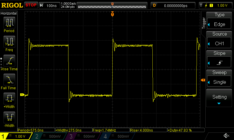
An oscilloscope trace of the "simple GPIO" benchmark running on ESP32-C6.
And let's look at the signal on the ESP32-C3 chip as well:
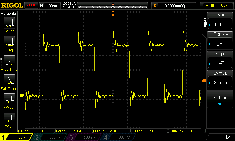
An oscilloscope trace of the "simple GPIO" benchmark running on ESP32-C3.
We're able to achieve a speed of about 1.74 MHz on the ESP32-C6 and 4.22 MHz on the ESP32-C3. Note that this is markedly less than the CPU clock speed of 160 MHz. This is could be due to a number of reasons:
-
The setter functions we use may cause a lot of CPU cycles to spent be simply calling the function and its helper functions, in between each actual signal change.
-
The simple GPIO output mechanism uses the microcontroller's APB bus to apply the output signals, and this bus runs at a lower speed (80 MHz) than the CPU itself, while possibly also introducing buffering delays.
-
The CPU clock speed describes the frequency with which CPU cycles are completed, and in the best case a single instruction is executed per CPU cycle. Even if we could effect an GPIO output value transition with a single instruction, we'd still always need two instructions to effect a full cycle of transitions (one instruction to go high, one instruction to go low). Hence, given a clock speed of 160 MHz, we can only hope to output at most a 80 MHz signal. We're clearly still quite far from that upper limit, however.
The first source of delays can be easily diagnosed as well as well mitigated, so let's take a look at that next.
Setter function overhead
To do so, let's take a look out the disassembled code for our benchmark for the
ESP32-C6 chip.1 The sequence of instructions corresponding to the busy
loop is as follows (note that I've omitted a few verbose bits marked with
...).
## Main busy loop
40808f16: ... li      a0,1024   # 1024 corresponds to bit #11, i.e. GPIO10.
40808f1a: ... auipc   ra,0x17fa
40808f1e: ... jalr    -1196(ra) # Function call to <...write_output_set...>
40808f22: ... li      a0,1024
40808f26: ... auipc   ra,0x17fa
40808f2a: ... jalr    -1200(ra) # Function call to <...write_output_clear...>
40808f2e: ... j       40808f16  # Loop back to the start.

## The write_output_set function.
42002a6e <...write_output_set...>:
42002a6e: ... lui     a1,0x60091
42002a72: ... sw      a0,8(a1)
42002a74: ... ret

## The write_output_clear function.
42002a76 <...write_output_clear...>:
42002a76: ... lui     a1,0x60091
42002a7a: ... sw      a0,12(a1)
42002a7c: ... ret
I'm not showing the generated code for the ESP32-C3 binary, but it looks practically identical. Given that the code is identical, it's quite interesting that the ESP32-C3 is able to achieve a much faster signal frequency than the ESP32-C6, right out of the box.
We can see that each iteration of the loop requires executing quite a few
instructions. I count 7 in the main loop and 3 more for each of the
write_output_set and write_output_clear functions (the
GpioPin::set_high/set_low functions seem to have been inlined by the
compiler, avoiding what would've otherwise been an additional function call).
This adds up to 13 instructions per iteration, just to perform two signal
transitions.
Even assuming a best-case scenario of one CPU cycle per instruction, this many instructions would only allow for a signal frequency of up to of 12.3 MHz, and that's likely an optimistic estimate since at least a few of the instructions will take longer than one CPU cycle to execute (e.g. some of the jump instructions).
On the other hand, the observed frequencies of 1.74 MHz and 4.22 MHz are quite far from that 12.3 MHz frequency anyway. This indicates that the instruction count is likely only part of the bottleneck. Let's see if we can reduce the instruction count, and see how much we can gain from that.
Benchmarking GPIO output with direct register manipulation
To reduce the loop's instruction count we can rewrite our benchmark to manipulate the GPIO output register directly via inline assembly instructions rather than via a function call. This will give us a clearer sense of the maximum GPIO output speed we can achieve using the simple GPIO output mechanism, which will still be limited by the APB bus speed.
!
A "simple GPIO" benchmark that toggles a single pin by manipulating the GPIO_OUT
registers directly.
Full source on Github.
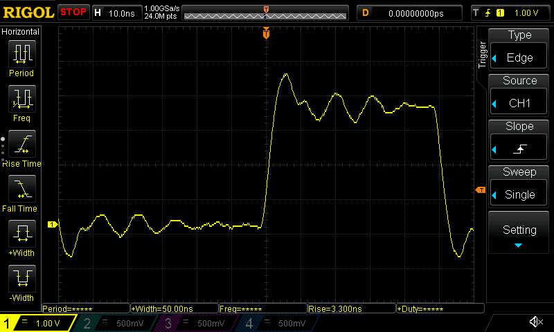
Let's take a look at the signal this generates on the ESP32-C6:
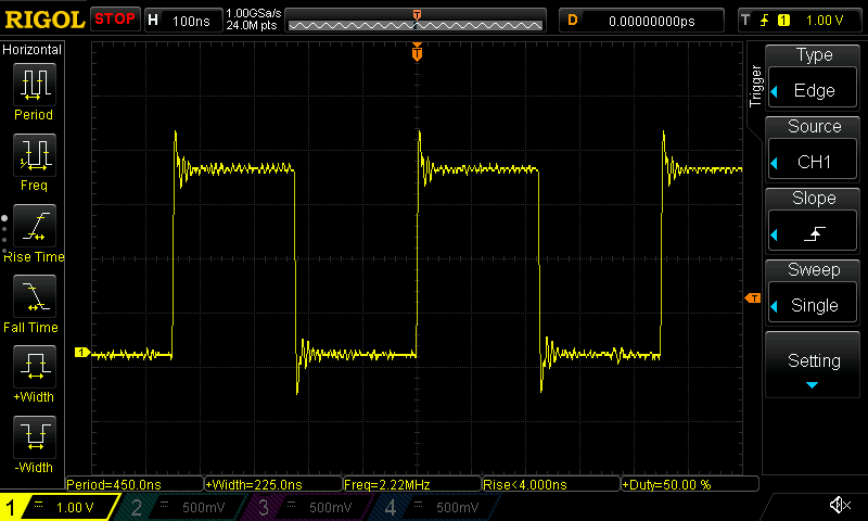
An oscilloscope trace of the "simple GPIO with direct register manipulation" benchmark running on ESP32-C6.
As well as on the ESP32-C3:
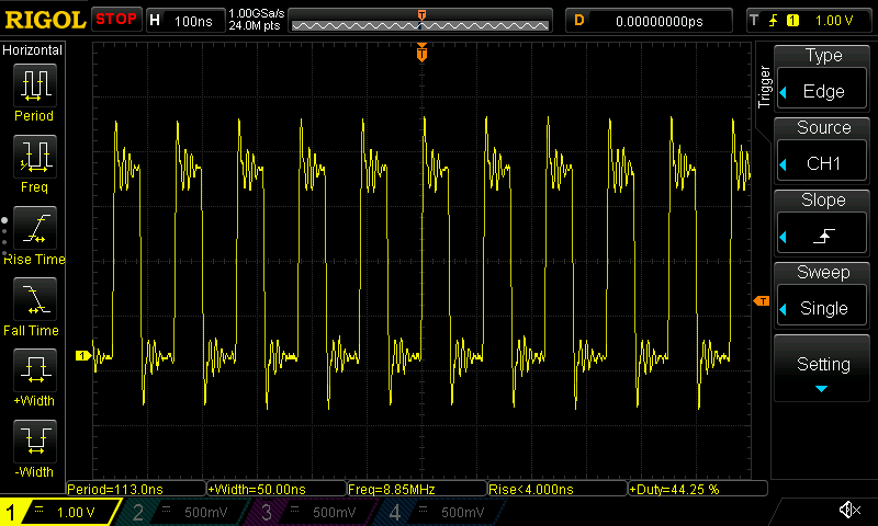
An oscilloscope trace of the "simple GPIO with direct register manipulation" benchmark running on ESP32-C3.
We're now reaching 2.22 MHz and 8.85 MHz on the ESP32-C6 and ESP32-C3, respectively. For the ESP32-C6 that's not a very big improvement (compared to the 1.75 MHz we reached before). For the ESP32-C3 it's almost a doubling in speed, but nevertheless the results are still lower than I'd like them to be, and at this point it seems we're clearly bottlenecked not by the instruction count, but by the underlying bus/peripheral speed. Fortunately, we can do much better than this.
Signal rise time
However, before I move on let's also take a quick look at the signal rise times for the previous benchmark, since that's another aspect of the signal waveform we might interested in. For the ESP32-C6:
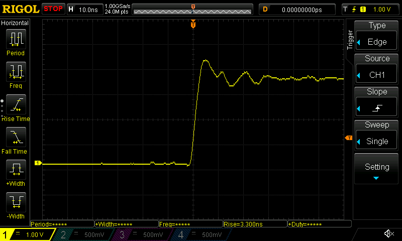
An oscilloscope trace of the signal rise time on ESP32-C6.
For the ESP32-C3:
An oscilloscope trace of the signal rise time on ESP32-C3.
We can see that in both cases the rise time calculated by the oscilloscope is approximately 3.3 ns. It defines rise time as the time it takes to go from 10% to 90% of a rising waveform.
The "dedicated IO" mechanism
Most of the microcontrollers in the ESP32 family support an alternate mechanism for doing GPIO that is distinct from the "simple GPIO" mechanism that we used in the previous sections, and which is more suitable for high-speed signaling. It is called "dedicated GPIO" in the ESP-IDF documentation, and "dedicated IO" in Section 14.1 of the ESP32-C6 manual, which describes the mechanism as follows (other ESP chips support the mechanism as well, but don't document it clearly in the manual):
Normally, GPIOs are an APB peripheral, which means that changes to outputs and reads from inputs can get stuck in write buffers or behind other transfers, and in general are slower because generally the APB bus runs at a lower speed than the CPU. As an alternative, the CPU core implements I/O processors specific CPU registers (CSRs) which are directly connected to the GPIO matrix or IO pads. As these registers can get accessed in one instruction, speed is fast.
To use this mechanism, you first need to configure the pin's function and
direction just like you would with the "simple GPIO" mechanism, but you
subsequently redirect the pin to be connected to one of the CPU_GPIO_OUT{n} IO
signals. The CPU has 8 such input/output signals, so we can drive or read up
to 8 pins this way.
The ESP-IDF framework defines APIs for configuring the pins for this mechanism,
as well as for manipulating the pins via setter functions. However, in order to
reap the benefits of the mechanism, the setter functions should be avoided. The
Rust esp-rs/esp-hal framework also supports the mechanism via its
GpioPin::connect_peripheral_to_output
API, by passing it one of the OutputSignal::CPU_GPIO_OUT{n} values.
In both cases, once the mechanism is configured, the GPIO output value of one
or more pins can then be set in a single CPU cycle by using the RISC-V
Control and Status Register instructions
to manipulate the CPU_GPIO_OUT CSR (address 0x805 on the ESP32-C3/C6 chips).
This means that with a clock speed of 160 MHz, we should be able to reach a maximum GPIO speeds of 80 MHz. Let's try it out.
Benchmarking GPIO output using dedicated IO
!
A benchmark that toggles a single pin using the "dedicated IO" mechanism.
Full source on GitHub.
Notice how similar it is to the previous benchmark, but how instead of writing to a memory location to set/clear the pin, we write to the CSR register. Let's take a look at the waveform this generates for the ESP32-C6:
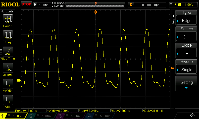
An oscilloscope trace of the "dedicated IO" benchmark running on ESP32-C6.
And on the ESP32-C3:
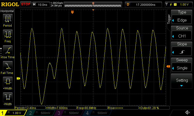
An oscilloscope trace of the "dedicated IO" benchmark running on ESP32-C3.
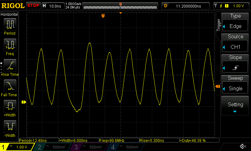
In this case, we see that we achieve a GPIO speed of about 53.2 MHz, with a lopsided duty cycle of about 32% on the ESP32-C6, while the ESP32-C3 reaches a 39.7 MHz frequency with a 27% duty cycle. Still not quite 80 MHz...
This is explained by the fact that we need three instructions to complete the benchmark's loop on the ESP32-C6 and each instruction takes one CPU cycle, meaning that the pin is held high for one CPU cycle but held low for two CPU cycles. On the ESP32-C3 the jump instruction seems to take two CPU cycles, so the signal is even more lopsided there, and the frequency even lower.
If we unroll the loop for a number of iterations then we should be able to reach a speed of 80 MHz, at least for short bursts. The following benchmark implements this approach.
!
A benchmark that toggles a single pin using the "dedicated IO" mechanism using 8
unrolled loop iterations.
Full source on GitHub.
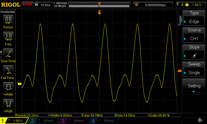
The following screenshots show that this way we are indeed able to reach 80 MHz signal frequencies for short bursts (note the wider gaps on the left sides of the screenshots, corresponding to the extra delay from the jump instruction at the end of the unrolled loop). On the ESP32-C6:
An oscilloscope trace of the "dedicated IO with unrolled loop" benchmark running on ESP32-C6.
And on the ESP32-C3:
An oscilloscope trace of the "dedicated IO with unrolled loop" benchmark running on ESP32-C3.
Note that because the signaling speeds are now getting to be so fast as to approach the signal rise times we observed earlier, the resulting waveform is now also much more sinusoidal than the waveforms we saw in the earlier benchmarks.
Emitting multiple signals simultaneously
Before I conclude this post, I want to highlight again that the dedicated IO mechanism allows us to manipulate up to 8 pins per CPU cycle. This means we can achieve high signal frequencies across multiple outputs simultaneously. For example, on the ESP32-C6 the following benchmark generates four 40 MHz signals in two groups of two, each group being 180 degrees out of phase with the other group.
!
A benchmark that toggles four pins simultaneously using the "dedicated IO"
mechanism.
Full source on GitHub.
The resulting waveform on the ESP32-C6 (note the clean 50% duty cycle):
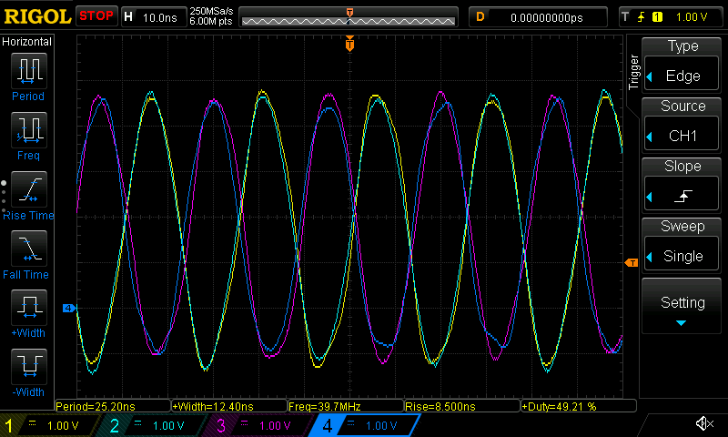
An oscilloscope trace of the "dedicated IO with four output signals" benchmark running on ESP32-C6.
On the ESP32-C3 the benchmark can't quite reach 40 MHz frequencies with 50% duty cycles, because the jump instruction takes two CPU cycles, resulting in five CPU cycles per iteration:
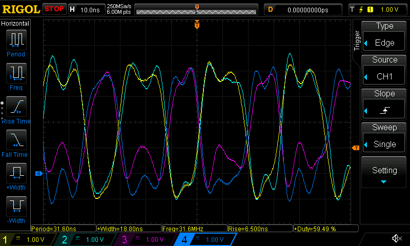
An oscilloscope trace of the "dedicated IO with four output signals" benchmark running on ESP32-C3.
Instead we see an imbalanced signal with a 40/60% duty cycle and a frequency of almost 32 MHz (since the 160 MHz CPU clock is divided by five CPU cycles).
What about the GPIO input speed?
So far I've focused solely on measuring the maximum GPIO output speed we can achieve, but that doesn't tell us anything about the maximum GPIO input speed we can achieve. That is, the frequency with which we can sample an incoming signal.
I won't attempt to define a benchmark to measure the input speed with in this post. However, just as the "dedicated IO" mechanism supports driving a pin output with every CPU cycle, it supports sampling an input pin value with every CPU cycle as well, albeit with a certain amount of sampling latency (two CPU cycles in the case of the ESP32-C6).
This means that on the ESP32-C3 and ESP32-C6, we could in theory sample signals with short bursts of a 160 MHz sampling frequency. When using a repeating loop like the one below we could reach sustained sampling frequencies of up to 80 MHz.
...
asm!;
...
However, remember that to reconstruct a signal with a bandwidth of $B$, it needs to be sampled at a sampling frequency of at least $2B$ (this is the Nyquist-Shannon sampling theorem). Hence, a sustained 80 MHz sampling frequency could only reconstruct signals with frequencies of at most 40 MHz.
And of course in practice you'd need to add a number of additional instructions to this most-minimal sampling loop, which would limit the the sampling frequency further. This is similar to how our benchmarks ignored various other delays you'd likely need to account for in practice as well. You'd likely need instructions to terminate the loop iteration, to store the sampled data into memory, etc.
So as a rule of thumb, we should probably reduce this maximum achievable sampling rate by a factor of 2x to 3x when considering real-world use cases. On the ESP32-C6 this means we should be able to successfully reconstruct input signals with bandwidths up to 13.33 MHz, perhaps even up to 20 MHz.
Conclusion
I've shown that while the the standard "simple GPIO" mechanism is limited to lower GPIO speeds, the "dedicated IO" mechanism provides a powerful alternative for doing high-speed signaling via GPIO. It can produce output signals with frequencies up to half of the chip's maximum CPU clock speed (which is 160 MHz for the ESP32-C3 and ESP32-C6 chips), since each signal change requires one CPU cycle.
| Result | ESP32-C3 | ESP32-C6 |
|---|---|---|
| Maximum burst output speed using dedicated IO | 80 MHz 50% duty cycle | 80 MHz 50% duty cycle |
| Maximum sustained output speed using dedicated IO | 32 MHz 40/60% duty cycle | 40 MHz 50% duty cycle |
| Maximum "simple GPIO" output speed using assembly code | 8.85 MHz | 2.22 MHz |
| Maximum "simple GPIO" output speed using setter APIs | 4.22 MHz | 1.74 MHz |
Summary of the GPIO output speed benchmark results.
The dedicated IO mechanism also supports sensing an input value every CPU cycle, which allows for sustained sampling frequencies of up to 80 MHz (enough to reconstruct signals with up 40 MHz of bandwidth, at least in theory).
The dedicated IO mechanism is available on both the ESP32-C3 and ESP32-C6, as well as most other chips in the ESP32 lineup. The ESP32-S2 and ESP32-S3 chips should be able to reach even higher output speeds of 120 MHz, given their CPU clocks go up 240 MHz. I didn't have any of those chips to test, however.
Note that these results should be treated as optimistic upper bounds. Depending on the specific use case the maximum signal frequencies that can be managed successfully are going to be lower. Nevertheless, having the ability to do such high-speed signaling using just GPIO opens up a number of interesting use cases. Even if we assume that in practice we'll be limited to only 0.5x or 0.25x of these speeds, that would make it feasible to bit bang many commonly used high-speed protocols with bandwidths up to 10 or even 20 MHz.
For example, since we know that a four CPU cycle loop reaches an output speed of 40 MHz, we can reason that to output a 10 MHz signal we would have 16 CPU cycles to spend per signal period, or 8 cycles per signal transition. This budget of extra CPU cycles should be enough to allow us to load the next bit to transmit from memory, perform conditional branches to handle the end of a data transmission, etc. between each signal transition instruction.
That's exactly what I'll try out in my next set of posts, as I'll attempt to write a bit banged Ethernet 10BASE-T implementation, which will require signal frequencies up to 10 MHz. Stay tuned!
Footnotes
I generated the disassembled code using the
riscv64-unknown-elf-objdump -d {the_binary} command on the binary
generated by the cargo build --release command. On Debian-based systems
the riscv64-unknown-elf-objdump utility can be installed using
apt install binutils-riscv64-unknown-elf.